
Like impacts from other weather and environmental forces (e.g., hail, wind, snow, wildfires), flood damage can often be prevented or at least mitigated through simple, no- to low--cost measures. The following technical recommendations can be added to project specification requirements of a new system or used to assist in planning for a modification to an existing solar PV system.
This webpage covers flooding topics related to on-site ground or elevated systems (e.g., solar PV canopies) for both new and existing systems. Though the lessons learned may also be applicable to utility-scale (large) systems, this content focuses on topics related to smaller on-site systems.
On This Page:
Even in severe cases such as large coastal floods from hurricanes, these mitigation measures can reduce the amount of damage that results from a severe flood event. In some cases, mitigation measures can make the difference between a total loss versus repairable damage.
Total SubmersionAny components for a solar system that have been submerged will need to be replaced and this includes the module, inverter, switchgear, meters and other hardware. |
Assessing a Site for Flooding Risks
A site can be flooded from a nearby coastal area, stream, river, or lake overflowing onto neighboring lands. Flooding also occurs when a high rate of precipitation (downpour) inundates the ability of the site to absorb the stormwater creating large areas of standing water.
A site does not need to be within a known flood plain (e.g., as defined by the Federal Emergency Management Agency, FEMA) to experience flooding. FEMA floodplain maps cover flooding from coastal and inland bodies of water (e.g., rivers, lakes, streams) but not from stormwater inundation. A site will need to be assessed using both FEMA flood maps and through the use of local information.
Use the resources below to understand the flood risks of a proposed solar system. Make adjustments to the proposed system to avoid any obvious areas that are of high risk for flooding.
Coastal and Riverine Flooding
Utilize the FEMA flood mapping tool by inputting the site's address and adjusting the zoom level to reveal the color-coded areas and symbols on the map. Within these maps, users will find many codes and symbols, but three key pieces of information are most relevant to a proposed solar site:
- 100-year flood level: A 100-year flood zone means that in a given year there is a 1% probability that a site will flood. This may sound like a low risk but consider that over a 25-year timeframe, there is a 22% probability, which is significant.
- 500-year flood level: A 500-year flood zone translates into an annual probability of 0.2%, or 4% over 25 years.
- Base flood elevation (BFE): The BFE is the 100-year flood level measured as feet above sea level.
This is an example from the FEMA flood map tool. Click on the icons to learn more about the various overlays.
The 100-year flood level (in blue overlay) shows areas where the level is below the base flood elevation (BFE). The black lines in Figure 1 shows 1,076 feet above sea level as the BFE in Figure 1.
Look to see if the site is within the areas covered by the blue overlay. Flood areas may not be shown with a blue overlay as more rural areas have not been audited in detail enough to provide map overlays. If there is no overlay at the proposed site, look to see if the proposed site's elevation is at or near the BFE shown on the FEMA map. Use a BFE value nearest to the proposed site. The elevation for a site can be found using commonly available mapping tools.
Flood levels are changing, so what was once a 100-year flood level may not be accurate currently. Table 1 summarizes flood scenarios and possible adjustments to the 100-year flood level.
Table: 100- and 500-Year Flood Decision Points
Scenario Recommended Action The proposed site is located within a 100-year flood zone with no recent history of flooding. Use 100-year level The proposed site is located within a 100-year flood zone with more than one flood event or events very close to flooding. Use a 100-year level with a safety margin; add 10% to the BFE elevation. The proposed site floods regularly. Use the 500-year level
Predicting future flood risks from sea-level rise & changing rainfall patternsIt is very difficult to predict what flood risks may be present on a site during a PV system's 25-30-year life. For coastal areas, the NOAA Sea-Level Rise Viewer tool can be used to estimate future flooding from sea level rise. The tool is easy to use and requires a street address or the name of a city and state. Make sure to click on "high-tide flooding" where the map displays areas that will be flooded in the future from the combined effects of sea-level rise and high tides. |
Stormwater Inundation
During a rainstorm, the ability of the soils to absorb and drainage systems to move water becomes overwhelmed causing a large amount of standing water. This is a common phenomenon and can occur at any site. Some sites are known to be vulnerable to stormwater inundation where standing water is often spotted during and after rainstorms.
As shown by the Photovoltaic Stormwater Management Research and Testing (PV-SMaRT) study, ground treatment and cover under the array field may reduce the ability of the site to absorb stormwater. This occurs from common ground treatment methods used with solar PV ground systems. Though this study focused on large utility-sized systems, some of the key discoveries are most likely applicable to the kinds of smaller ground systems found on federal sites.
Solar PV Modules Classification in Some StatesSome states define the surface area of the module as impervious while others provide an exemption. For new projects, the PV-SMaRT study (see Table 2 on page 11) provides a summary of states that have standards to address solar PV systems and groundwater management. |
Hills are not immune from stormwater inundation. Sometimes these locations are on the flow paths from water moving downhill. These water flows will have a lot of velocity and can wash away enough soil to undermine the foundation piles and equipment pads. Array locations on the bottom of a hill can be particularly susceptible to water flows coming from above.
Measures To Prevent Flood Damage
Inspections of flooded sites reveal opportunities to reduce or even eliminate the damage and thus reduce recovery costs and time following a flood event. Agencies can implement measures (many low-cost) to mitigate or prevent damage to both proposed and existing systems.
Structural Engineering Measures
Applicable to: New systems
Benefit Description Prevents total loss of solar modules and electrical equipment If the modules and electrical equipment become submerged (even if only partially) then the system is likely a total loss. Quick recovery after flood Keeping modules and electrical equipment above flood levels will facilitate quick recovery after flood. Higher array elevation supports pollinators Greater height may allow for the establishment of deep-rooted pollinators and native plantings under the array. Use the FEMA and NOAA resources provided under Assessing a Site for Flooding Risk to help determine a reasonable equipment height above the predicted flood level.
Systems placed at higher elevations will add cost to racking systems and equipment pads for inverters and switchgear, so there should be a discussion with project engineers about acceptable long-term storm risks and project costs.
Figure 2 depicts solar arrays and electrical equipment at an elevation above the predicted flood level.
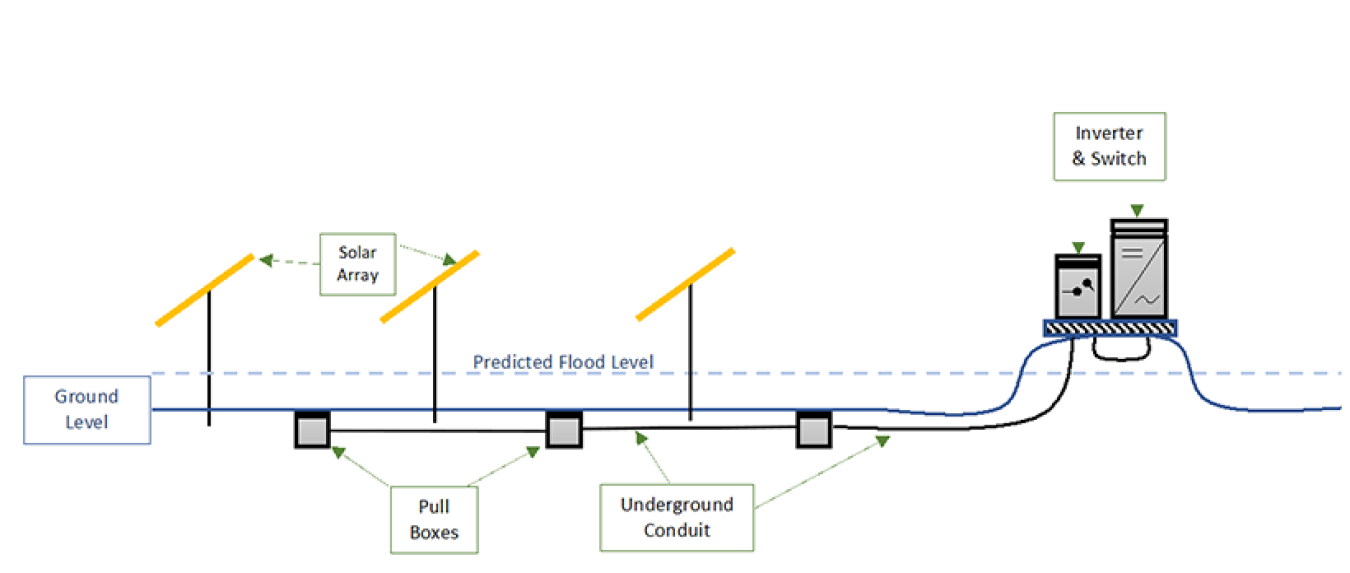
Figure 2. Elevating array field and electrical equipment above predicted flood level.
Gerald Robinson, Lawrence Berkeley National LaboratoryApplicable to: New systems
Benefit Description Enable system longevity for those exposed to soil with high moisture Foundation piles and equipment pads are designed to withstand exposure to wet and corrosive soils. Foundation piles and equipment pads will likely be designed assuming dry soils. Foundations that experience extended periods of high moisture may not properly support the solar arrays, experience excessive corrosion (thus weakening over time), and in cold climates may experience a phenomenon called "frost jacking" (i.e., the upward force exerted on foundation piles from soil freezing and expansion).
Require that foundation piles and equipment pads be specified using wet soil conditions to address both structural integrity and corrosion issues (which can lead to structural failures). Foundation piers are to be hot dip galvanized (ASTM standard) and the rebar in equipment pads is to be coated.
Electrical Engineering Measures
Applicable to: New systems
Benefit Description Prevents water intrusion into electrical enclosures Any water flowing downhill can drain and be prevented from entering electrical enclosures. 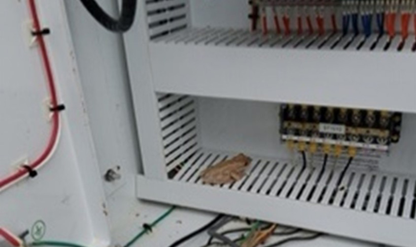
Figure 3. Inverter following flooding, a frog was washed inside.
Gerald Robinson, Lawrence Berkeley National LaboratoryStormwater and floodwater have entered electrical pull boxes in the array field and then flowed downhill to the electrical switchgear and inverters.
Figure 3 shows how a frog was conveyed into an inverter enclosure through conduit flooding.
Figure 4 shows how floodwaters can enter pull boxes and end up in the cabinets of electrical equipment.
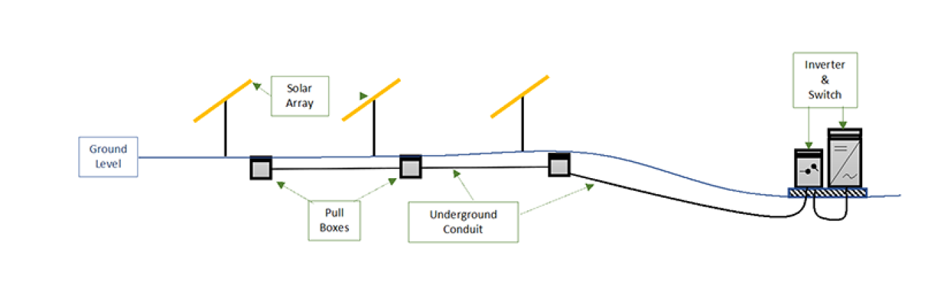
Figure 4. Risk of conduit conveying flood water to electrical equipment and inverters.
Gerald Robinson, Lawrence Berkeley National LaboratoryConduit can be modified to provide a means for water to drain and avoid entry into electrical enclosures (Figure 5).
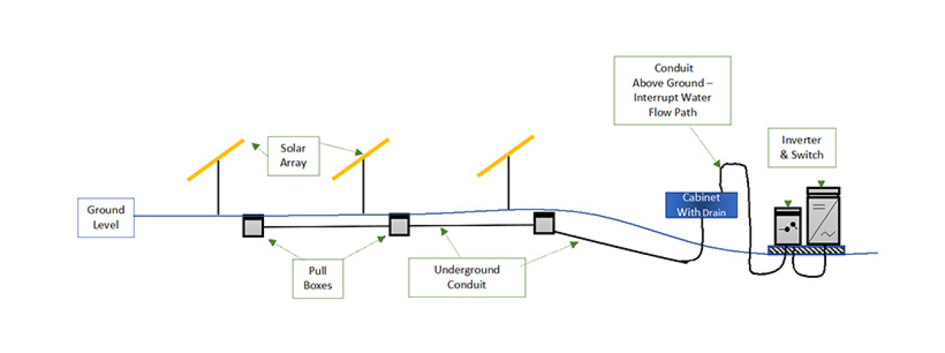
Figure 5. Modifying conduit run to prevent flooding into electrical equipment and inverters.
Gerald Robinson, Lawrence Berkeley National LaboratoryApplicable to: New and existing systems
Benefit Description Protects sensitive electrical equipment and supports longevity Some inverter and all electrical switchgear manufacturers provide cabinet options. Specify NEMA 4 ratings (or NEMA 4-R ratings, if in coastal setting) for all cabinets, including those related to metering and communications. During heavy rains with strong winds, large volumes of water can enter electrical enclosures that are under specified flooding sensitive and costly electrical equipment. A typical solar PV system has a few main pieces of electrical equipment such as inverters, switches, and breaker panels which will need more frequent replacements if the enclosures are not rated to provide adequate protection.
Minimally require NEMA 3 enclosures and, if corrosion is common at the site, require NEMA 3-R ratings. If a site experiences frequent heavy wind driven rains and high humidity, the use of NEMA 4 (and 4-R) may be warranted. If equipment is indoors (e.g., inside utility rooms), a lesser rating would be sufficient.
Additional Measures
Applicable to: New and existing systems
Benefit Description Common and well understood measures Many civil engineers, local authorities, and contractors are very familiar with these features. Reduce soil scour (erosion) Through diversion, these features can move water around or away from solar PV equipment, preventing foundation piles and equipment pads from getting undermined. This prevents soil from leaving the site and polluting rivers, streams or neighboring properties. Local authorities may not require stormwater management features; however, agencies should follow the guidelines issued by the U.S. Environmental Protection Agency. There have been examples of projects lacking important (and required) stormwater management features resulting in significant but avoidable damage to solar PV systems. These features (e.g., retention areas, swales, French drains, dry wells) can be added to new and existing systems and could be combined with pollinator plantings.
Applicable to: New and existing systems
Benefit Description Reduce stormwater flows Absorb more stormwater into site soils and plantings. Reduce soil scour (erosion) Reduce the volume and velocity of water flows through the site resulting in more retained soils. May reduce project cost New systems may need less site preparation work if utilizing a pollinator strategy. Provide pollinator habitat Support bee and butterfly populations. Standard practice with site preparation for ground-mounted systems results in topsoil loss, compaction, and sometimes use of gravel, and or geotextile weed cloth, greatly reducing the ability of the site to absorb stormwater.
The ability of a site to absorb a greater amount of stormwater can be recovered and possibly improved (depending on site conditions) through the use of deep-rooted pollinators and native plants.
These plants loosen soils, allowing stormwater to soak in, and the plant roots also absorb a large amount of water. PV-SMaRT research has shown a reduction of stormwater by as much as 38% from this strategy.
Ideally, a solar PV system should be designed to support pollinator plantings (row spacing and height off the ground), however, existing systems might be able to sustain pollinators around the perimeter and possibly between rows.
For new systems, please see the pollinator specification found in the FEMP Technical Specifications for Onsite Solar Photovoltaic Systems tool.
For new systems, it is possible that the use of pollinators can reduce project costs by reducing the site preparation work. By reducing ambient air temperatures, pollinators have been shown to increase system efficiency as well.
Additional Resources
Toward Solar Photovoltaic Storm Resilience: Learning from Hurricane Loss and Rebuilding Better
General Services Administration Explores Solar Photovoltaic Storm Resilience After Hurricane Damage
Severe Weather Resilience in Solar Photovoltaic System Design
Solar Photovoltaic Systems in Hurricanes and Other Severe Weather

Contact FEMP for assistance with solar PV systems.