
The Federal Energy Management Program (FEMP) offers strategies for water efficiency in cooling systems that feature cooling towers in new and existing federal data centers and provides agencies with resources to identify potential water-saving opportunities for these water-intensive applications.
Typical Data Center Cooling System
Figure 1 offers a simplified schematic of a typical data center that relies on evaporation from a cooling tower as the last stage of heat removal from the facility.
The red lines depict the flow of heat with the thicker lines representing air flow streams and the thinner lines representing water flow. The blue lines depict the flow of cooling sources and the light blue space at the bottom of the data center facility illustrates a raised floor plenum space to allow cool air to be isolated and directed to the heat source.
The heat generated from the information technology (IT) equipment (shown in the schematic as air-cooled IT racks) is pulled from the room by the computer room air-conditioning system, where the heat is transferred to the chilled water system. The chiller transfers the heat from the chilled water loop to the condenser water loop, and the condenser water loop carries the heat to the cooling tower where the evaporative process extracts the heat and dissipates it to the surrounding atmosphere.

Low-Cost/No-Cost Water-Saving Opportunities at Existing Data Centers
The process is energy intensive, with data center IT equipment operating 24 hours a day and requiring cooling on a continuous basis. Data center energy performance can be tracked in terms of power usage effectiveness (PUE), which is the ratio of the total annual facility energy use to the annual energy use of all of the IT equipment.
Mathematically, it is a dimensionless ratio of the facility’s total energy use to the energy use of the IT equipment as shown in the following equation:
PUE = (Total Facility Annual Energy Use (kWh))/(IT Equipment Annual Energy Use (kWh))
According to FEMP’s Best Practices Guide for Energy-Efficient Data Center Design, data centers with average energy efficiency have a PUE of 2.0 while recent advancements have allowed highly efficient data centers to approach the theoretical minimum PUE of 1.0.
In terms of water use for data centers that rely on cooling towers for process cooling, overall consumption is directly related to the heat load created by the IT equipment, other data-center loads, and the efficiency of each step in the removal of heat from these loads. Data center water performance can be measured through water usage effectiveness (WUE). This is a site-based metric that defines how efficiently a facility or location uses water in relation to the energy consumption of the IT equipment, with units of liters per kWh, mathematically expressed by the following equation:
WUE = (Annual Site Water Usage (liters))/(IT Equipment Annual Energy Use (kWh))
A variety of low-cost, no-cost, operations and maintenance (O&M) related water-saving opportunities may be options for existing data centers to pursue. Areas to consider include, but are not limited to, the following.
Space temperatures in data centers are frequently controlled well below recommended set points, while humidity is often over-controlled at a very narrow range. This practice offers no operational benefits but directly correlates to high chiller demand and excessive water use from the cooling tower system for removal of heat from the facility. Similarly, excessively narrow control of space humidity for data centers where humidity controls are not centralized can result in adjacent systems fighting to meet the humidity set point.
One system may be dehumidifying while the other is adding humidity to the space. This also increases the energy use and water use of the facility. ASHRAE provides specific guidance on the recommended operating conditions for equipment in data centers in their publication Thermal Guidelines for Data Processing Environments, 4th Edition. Depending on the operational availability of the data center (referred to as the data center type classification), the altitude, and other variables, ASHRAE recommends operating temperatures up to 80°F and humidity ranges from 20% relative humidity and 42°F dew point temperature up to 60% relative humidity and 59°F dew point temperature for IT inlet air conditions, with even broader thresholds for allowable temperature and humidity conditions in the facility.
Raising the set point for temperature and increasing the range of humidity control set points in the space will result in energy savings and will also result in water savings by reducing the amount of heat that needs to be dissipated by the evaporative process at the cooling tower system. Expected savings vary depending on the magnitude of changes to space temperature and humidity set points as well as outdoor air temperature and humidity. Additionally, raising the temperature set point and broadening the minimum and maximum humidity allow for more annual hours when the facility can take advantage of air-side economizing strategies that use cool ambient air to condition the space rather than relying on the chiller and cooling tower system. For a summary of the ASHRAE recommendations, see FEMP’s Best Practices Guide for Energy-Efficient Data Center Design.
Space airflow characteristics are also important to understand and consider when reviewing the cooling system performance for a data center. Modern IT equipment configured in racks, as shown in Figure 1, produces concentrated heat loads from the exhaust of the servers. Organizing the racks and configuring them in such a way to isolate the heat loads and have distinct hot and cool zones is critical to efficient operation and maximizing the effectiveness of the cooling system.
The warm air should be removed from the space in a manner that restricts mixing with the cool air supplied to the IT equipment intakes. Figure 1 depicts these conditions with separate hot air and cool air zones, or aisles, around the IT equipment. Cool air is supplied from the underfloor plenum while the warm air from the hot aisle is returned to the cooling equipment. A variety of hot aisle/cold aisle isolation methods are available, including flexible plastic barriers that act as partitions above and along the sides of the IT racks.
These practices enable the use of higher chilled water temperatures and reduced air flow which can result in 20% less energy consumption at the chiller according to FEMP’s Best Practices Guide for Energy-Efficient Data Center Design, which will directly correlate to less water use at the cooling tower by reducing the amount of heat that needs to be dissipated by the evaporative process.
An effective means of economizing in heating, ventilation, and air-conditioning (HVAC) systems is the use of cool outside air to provide cooling to the interior of a facility rather than relying on the mechanical cooling system. Because data centers operate 24 hours per day, they require a fairly consistent cooling load independent of the outside air temperature, which makes these facilities excellent candidates for air-side economizing strategies when the outdoor air conditions are cool at night or during mild weather times of the year (typically during the spring or fall, depending on the climate zone).
Air quality and humidity tolerance levels are considerations, so it’s important to thoroughly evaluate an effective control strategy to ensure the IT equipment is protected from contaminants and high humidity conditions. However, capitalizing on effective air-side economizing strategies can result in significant cooling system energy and water reductions. (Savings will depend on several variables, including climate, data center temperature and humidity set points, and the number of hours air-side economizing is used to replace mechanical cooling.) For more information on the considerations of air-side economizing, refer to Pacific Gas and Electric’s Data Center Best Practices Guide and Lawrence Berkeley National Laboratory’s Humidity Control in Data Centers.
Another effective strategy that can reduce water and energy consumption in data centers is water-side economizing, provided the cooling system is configured with an integrated heat exchanger that can by-pass the chiller and use the cooling tower to directly cool the chilled water loop during mild outdoor conditions. In this scenario a heat exchanger (often a plate and frame heat exchanger) is incorporated to cool the chilled water loop directly from the cooling tower, bypassing the chiller and eliminating the heat rejection from the chiller’s compressor, which can contribute up to 20% of the total heat demand to the overall heat rejection requirement of the cooling tower system. If the heat exchanger is located upstream and in series with the chillers, rather than in parallel, the water-side economizer can be used as a first stage of cooling for the chilled water loop, reducing the load on the chiller, and reducing the overall heat rejection requirement, thereby saving water and energy.
For more information on the considerations of air-side economizing, refer to FEMP’s Best Practices Guide for Energy-Efficient Data Center Design.
A cooling tower system by necessity uses an extensive amount of water because the warm water from the chiller’s condenser water loop is cooled by evaporating water into the surrounding atmosphere (see Figure 1). This water demand is particularly high for constant demands such as data center cooling. Water use at the cooling tower results primarily from the evaporative process; however, some of the water will also be drained (known as "blowdown") from the system to maintain consistent dissolved mineral content in the recirculating condenser water loop. (As water evaporates from the system, the concentration of dissolved minerals in the water increases.)
Cycles of concentration is a term used to describe the ratio of the volume of water supplied to the cooling tower (often referred to as makeup water) to the volume of blowdown water, and correlates to the effective water use in the system. High cycles of concentration are directly related to low levels of blowdown. Maximizing cycles of concentration minimizes the volume of water consumed by the cooling tower system for blowdown purposes, which reduces the volume of water needed for supply or makeup. It is common for systems to operate at two to four cycles of concentration, while six cycles or more may be possible.
According to FEMP’s Cooling Tower Best Management Practice, increasing cycles from three to six reduces cooling tower makeup water requirements by 20% and cooling tower blowdown by 50%. For more information on best management practices for water efficiency of cooling towers, refer to FEMP’s Cooling Towers fact sheet.
Thermal storage is a method of using the mechanical cooling system during off-peak, nighttime hours in cool, dry climates to fill a chilled water storage tank or in some cases to make ice. The stored chilled water or ice can then be used during peak, daytime hours to reduce the demand on the mechanical cooling system. Thermal storage options are particularly beneficial at locations with high daytime utility costs as a means to peak shave and are also an economical alternative to additional mechanical cooling capacity. The drawback of thermal storage is that the water and energy savings may not be significant because it still relies on the mechanical cooling system and the evaporative process and it also minimizes the possibility of air-side economizing, which has the potential of greater reductions in energy and water use in cool, dry climates.
Side stream filtration systems remove suspended solids, organics, and silt continually from a portion of the recirculating condenser water loop. This significantly reduces fouling and microbiological growth in the cooling tower fill and in the heat exchange surfaces in the chiller and also helps reduce the scaling potential and corrosion-related challenges that can negatively affect the transfer of heat in the chiller or in the cooling tower. A variety of side stream filtration types are commercially available, including centrifugal separators, automatic screen filters, plastic disc filters, and sand filtration systems. For more information, refer to FEMP’s Side Stream Filtration for Cooling Towers.
Implementing these systems on large evaporative cooling tower systems helps them to operate at or near optimum efficiency, maintaining near-design energy and water consumption. For cooling tower systems that are heavily fouled and operating poorly, implementing a side stream filtration system will improve efficiency and enable the cooling tower system to operate at or near design efficiency. However, side stream filtration systems will not reduce the facility’s power consumption or water use without additional technologies or operational modifications that reduce the cooling demand from the IT equipment.
Reverse osmosis (RO) filtration systems use pressure to force water through semi-permeable membranes to remove dissolved solids and other large molecules, producing high-quality effluent (called permeate). The majority of the dissolved solids and large molecules are concentrated into a reject stream that is discharged. RO systems are used commercially for seawater desalination and for producing high-purity water for microelectronics, boiler feed water, laboratory rinse water, and biotechnology.
For data centers located in drought-stricken regions or where increasing freshwater demands threaten ongoing operational needs for water resources, implementing an RO filtration system on the cooling tower blowdown is an option to offset some of the facility’s freshwater needs. The purified permeate from the RO system can be reused as cooling tower makeup water, which will reduce the facility’s overall water consumption. However, implementing an RO system will negatively affect the facility’s overall PUE due to the high energy demand of RO systems and will create additional O&M needs and costs. For more information on RO systems, refer to FEMP’s Reverse Osmosis Optimization.
Direct liquid cooling systems transfer the heat generated from the IT equipment directly to a recirculating chilled water loop rather than transferring the heat to the room air and then moving the heat from the air to the chilled water loop. Figure 2 is a simplified schematic of a liquid-cooled system, illustrating the flow of heat from the IT racks to a closed water loop that carries the heat to a coolant distribution unit (CDU) where the heat is transferred to the condenser water loop and taken to the cooling tower system. In this scenario, the air temperature in the space is maintained by a direct-expansion (DX) cooler that directly cools the air in the space using a refrigerant vapor compression/expansion cycle rather than relying on a chilled water system.
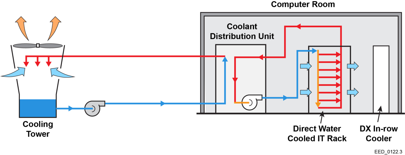 Figure 2: Schematic of a Direct Liquid Cooled System
There are many variants, including systems that use computer room air handlers (CRAHs) connected to chilled water systems to cool the air in the computer room while the IT equipment is cooled by CDUs. Some systems are compressor-free, as shown in Figure 2, while others reject heat to chilled water at the CDU, which then goes through a chiller to the cooling tower, similar to the schematic in Figure 1.
Some of these systems are showing great promise at reducing both the PUE and WUE of data centers, as pumping systems are typically more efficient than fans and water can carry significantly more heat than air. Successful applications of direct liquid cooling systems are being demonstrated at Sandia National Laboratories and the National Renewable Energy Laboratory (NREL).
These systems integrate direct liquid cooling with an air-cooled heat rejection system with an open cooling tower as a final step for rejecting process heat to the atmosphere. The hybrid cooling system, called the Thermosyphon Cooler Hybrid System, relies on the open cooling tower during peak, daytime hours to remove the heat from the recirculating loop between the cooling tower and CDU, and can switch over to the air-cooled heat rejection system when ambient outside temperatures are cool. The system is also able to operate in series and use the evaporative cooling process in conjunction with the air-cooled heat rejection system based on feedback loops balancing heat rejection requirements from the IT equipment and the outdoor air conditions.
The data center at NREL achieved a highly efficient PUE of 1.06 and a WUE of 0.7 (see Lessons Learned from the World’s Most Energy Efficient Data Center). While achieving great success, these systems introduce several additional control loops that must be maintained, operated, and monitored. Proper design and implementation should be considered along with a detailed O&M plan to ensure switchover sequences function as designed. For more information, see NREL’s Thermosyphon Cooler Hybrid System for Water Savings in an Energy-Efficient HPC Data Center: Modeling and Installation.

Best Practices for Comprehensive Water Management for Federal Facilities